
19 jobs
Lost circulation while drilling
Partial, severe and total losses, including depleted zones and wide fractures
THERMOGEL and THERMOGEL HT are solids-free fluids. They are pumped as liquids and turn into an elastic gel inside the formation, sealing fractures, channels and leaks during drilling, workover and restoring the tightness of well casings.
Partial, severe and total losses, including depleted zones and wide fractures
Selective isolation of water inflow in producing wells
Improving the injection profile in injection wells
Isolation of permeable intervals and annuli before abandonment
Sealing gas leaks through casing threaded connections and wellhead seals; annulus pressure disappears or drops substantially
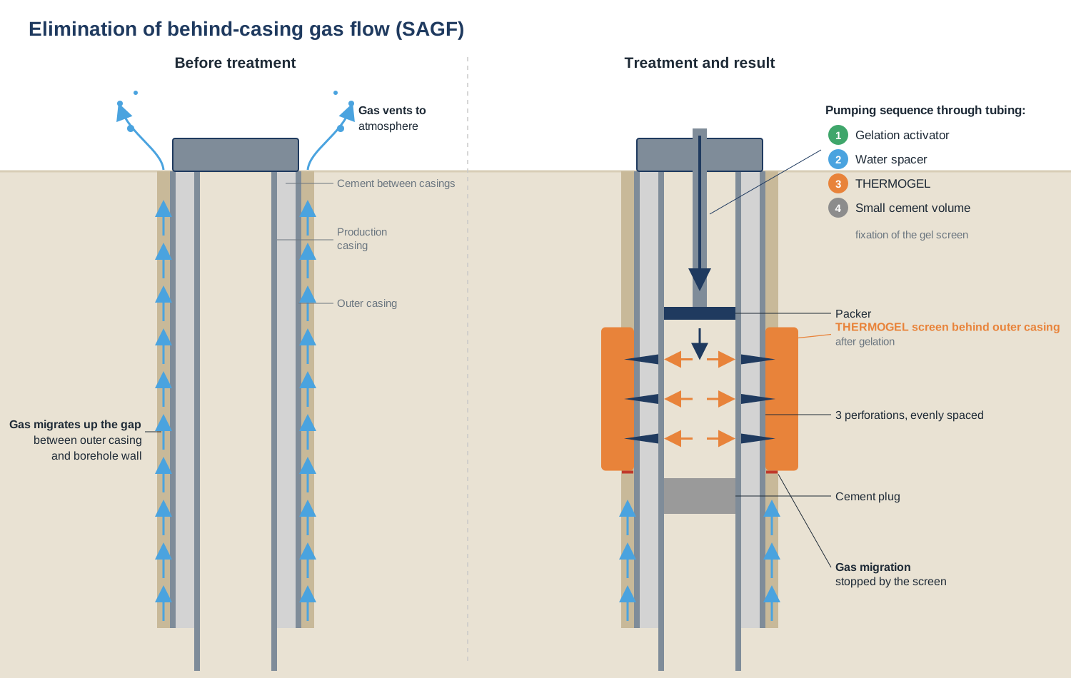
Sealing of gas migration channels behind casing that feed gas venting through the ground around the wellhead
Two systems, chosen by bottomhole temperature. Both are solids-free, low-viscosity fluids that pass through MWD/LWD tools, mud motors and bit nozzles, and both are mixed and pumped with standard rig or cementing equipment.
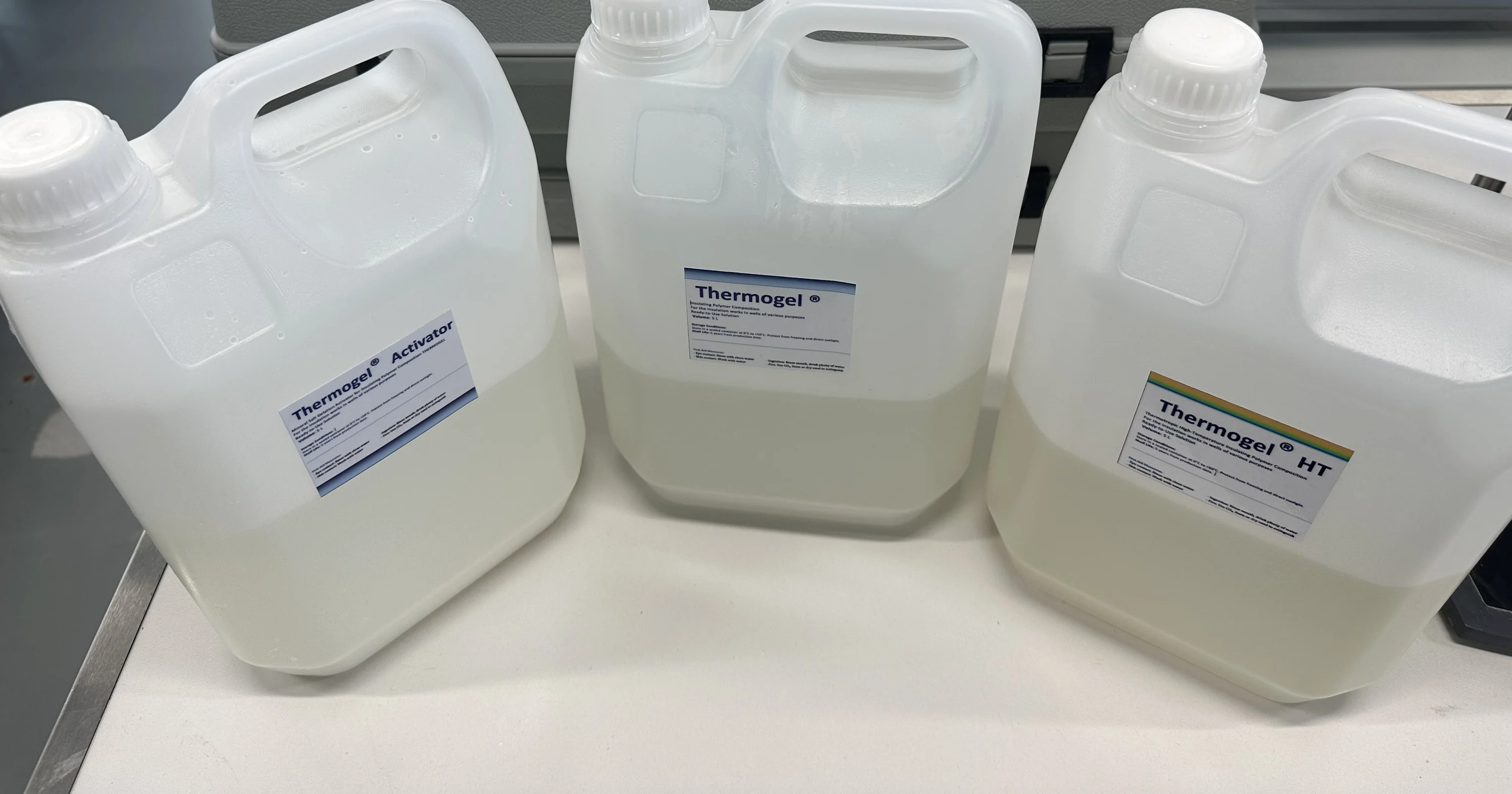
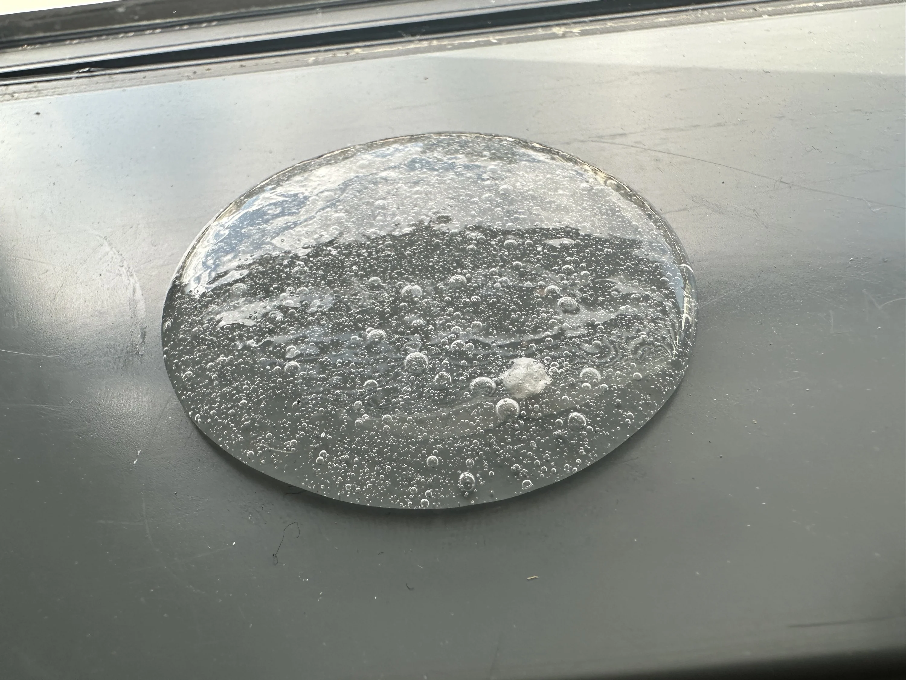
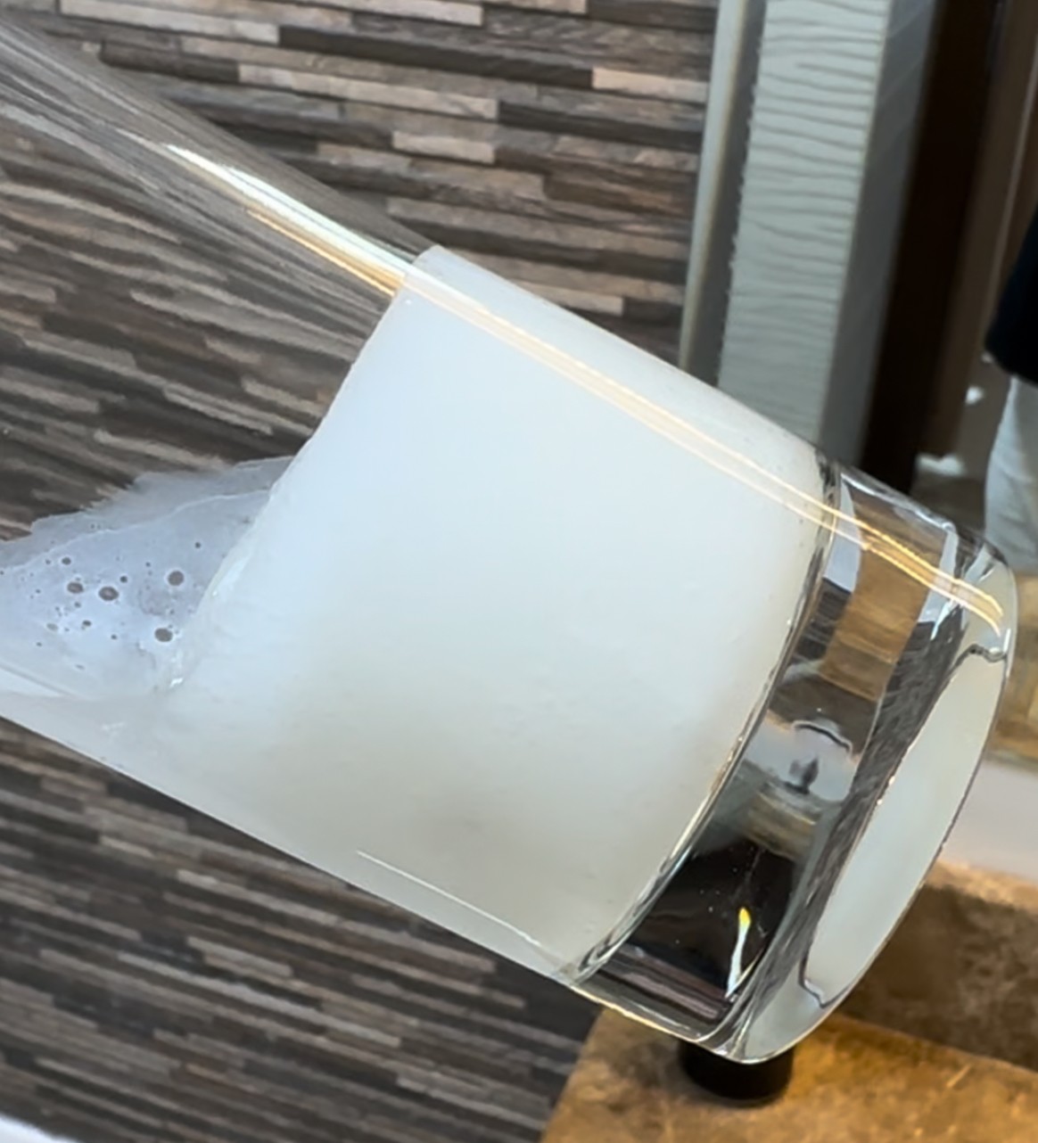
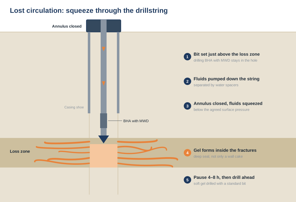
THERMOGEL enters fractures and channels as a liquid and gels inside them. The seal is formed in depth, not only as a filter cake at the wellbore wall, so the zone holds when mud weight or ECD goes up.
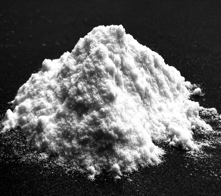
Total losses with no returns: staged injection with support on bottom. Wide fractures and caverns: a bridging stage with LCM or dry THERMOGEL powder first, then the gel. THERMOGEL is used where LCM pills and cement plugs have failed.
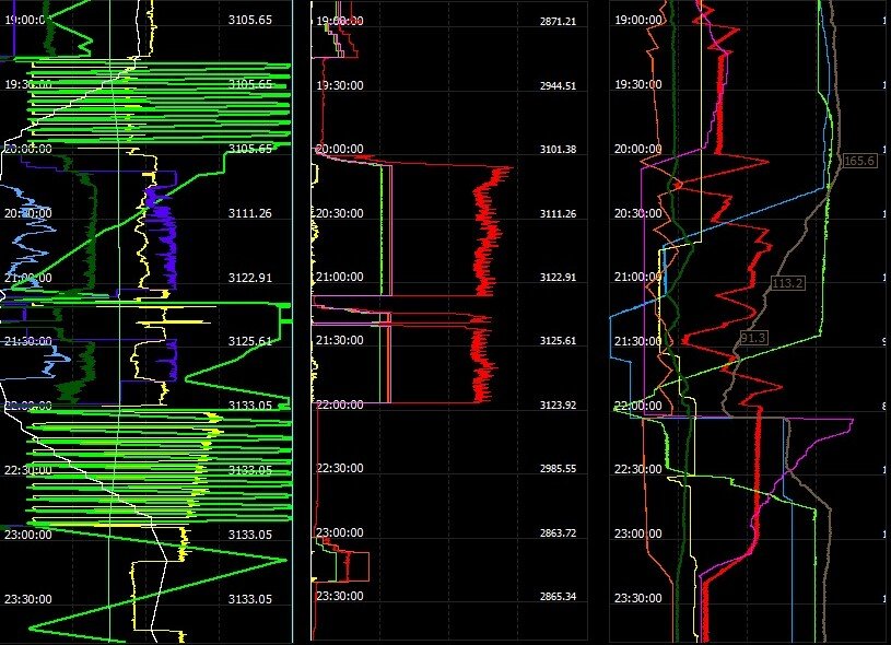
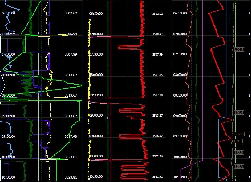
THERMOGEL HT is placed across producing intervals for selective water shutoff. Example: after treatment a producing well flowed water-free at about 70 t/d of oil and 45,000 m³/d of gas.
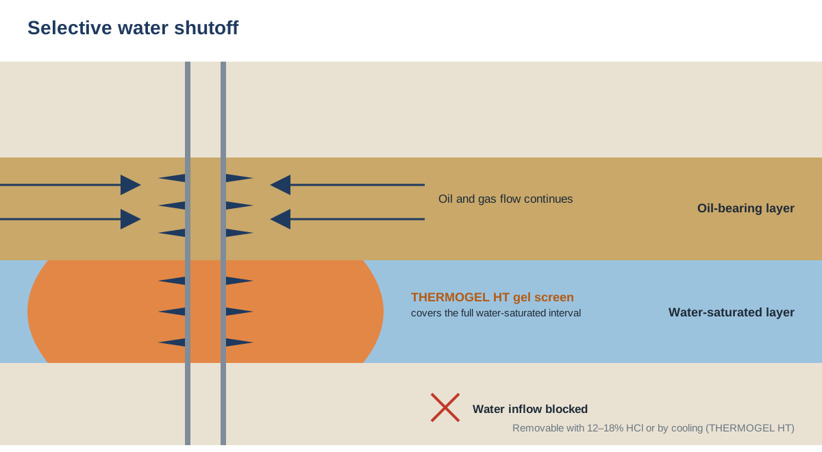
In injection wells the gel screen improves the injection profile for 3–5 years.
Both gels are removable with 12–18% hydrochloric acid; THERMOGEL HT can also be liquefied by cooling. Before work in a reservoir we run return-permeability and compatibility tests on the client's core and fluids.
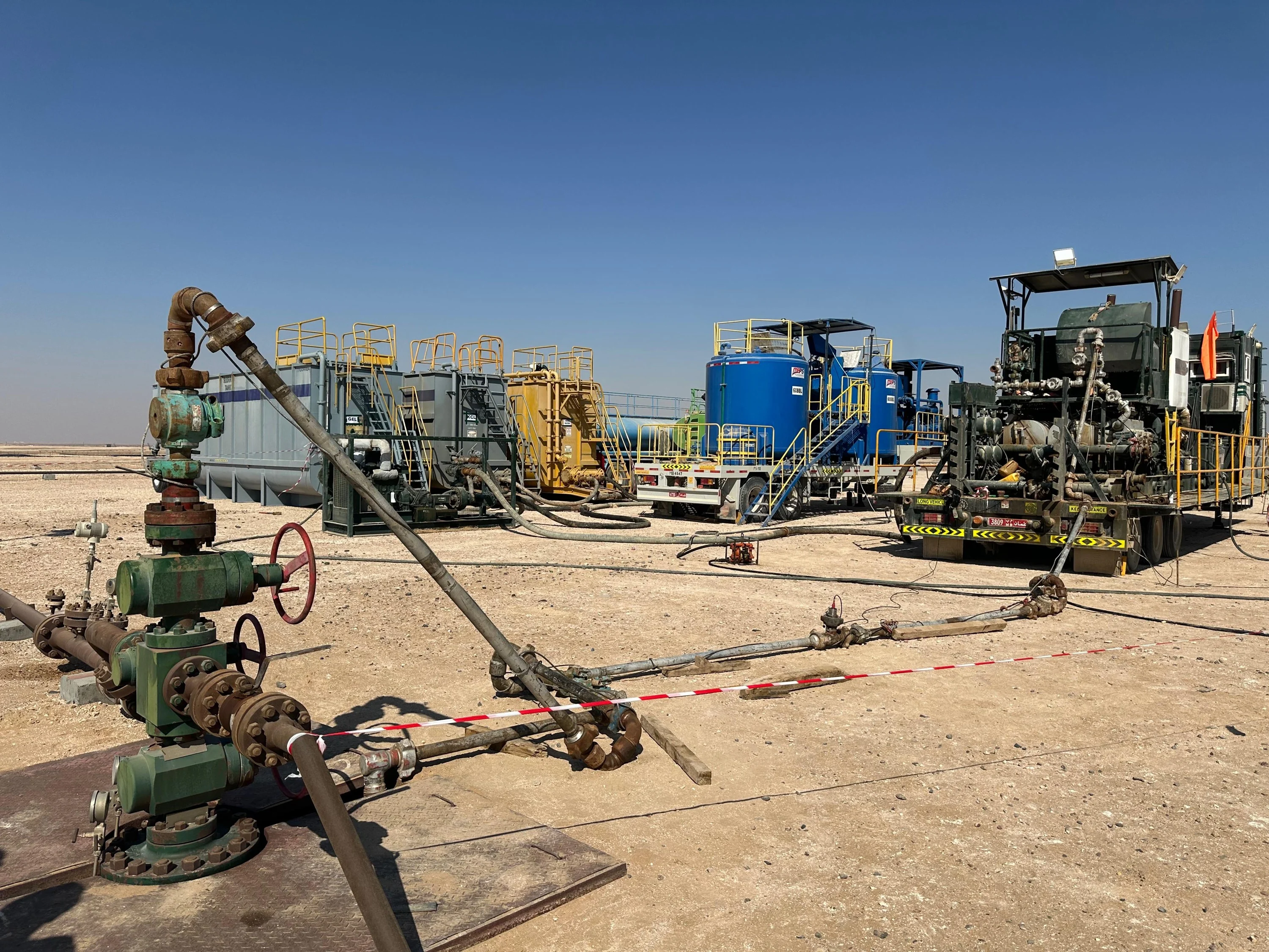
Wellhead and pumping equipment ready for a conformance treatment in an injection well
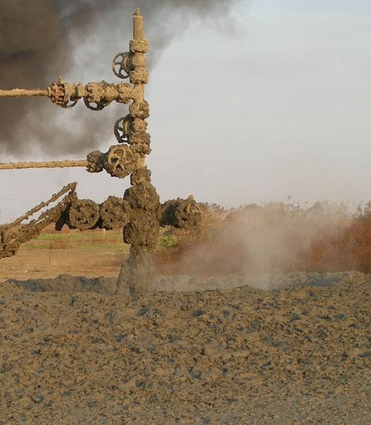
Sustained casing pressure (SCP) and surface annular gas flow (SAGF) can lead to uncontrolled gas releases, fires and explosions.
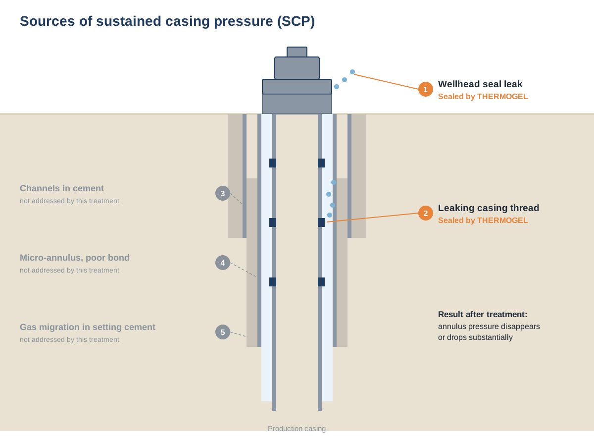
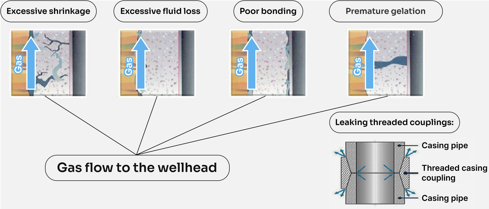
SCP: gas pressure builds up in the annulus between casing strings and can escape through the wellhead seals.
SCP has many possible sources. Our SCP treatment removes two of them: gas leaking through casing threaded connections and gas leaking through wellhead seals.
Result: after treatment the annulus pressure either disappears completely or drops substantially.
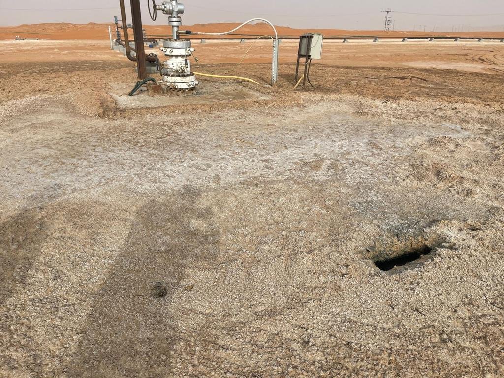
SAGF: gas migrates outside the well and vents to surface through the ground around the wellhead (gas griffons).
The gas migration channel is sealed during a standard workover. This extends safe, trouble-free operation of ageing wells.
Tested in April 2026 by an independent drilling and cementing fluids laboratory. In the disc and core tests the limit was the test cell (700 psi), not the gel. Full report available under NDA.
| THERMOGEL model | Pressure held | Gel penetration |
|---|---|---|
| Leaking threaded connection, 1/4" | 150 bar (2,200 psi), stopped for safety | — |
| Channel in cement, 1.0 mm | 60 bar (870 psi) | 2–3 cm |
| Core disc 8,000 mD | 48 bar (700 psi), cell limit | 3–5 mm |
| Core 0.25 mD | 48 bar (700 psi), cell limit | 0.5–2.5 mm |
| Proppant-pack fracture, 300 D | 17 bar (250 psi) | 3–4 cm |
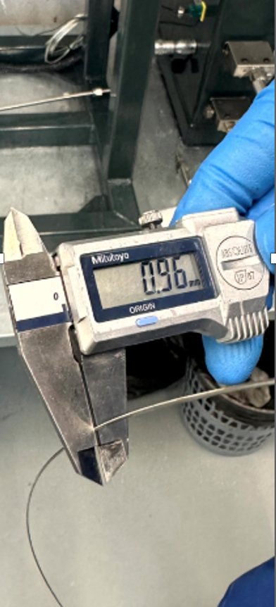
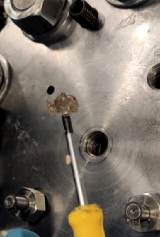
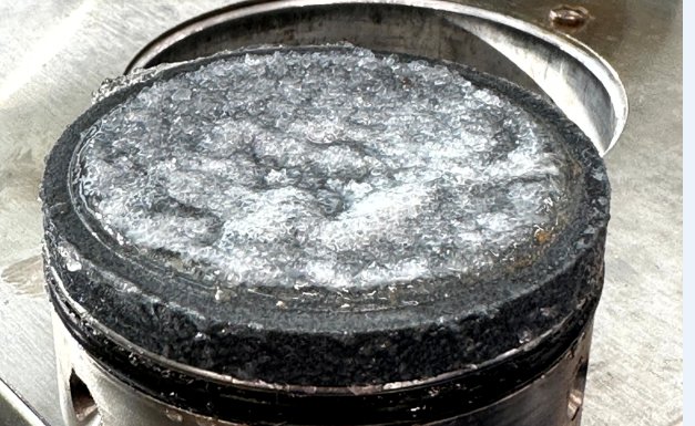
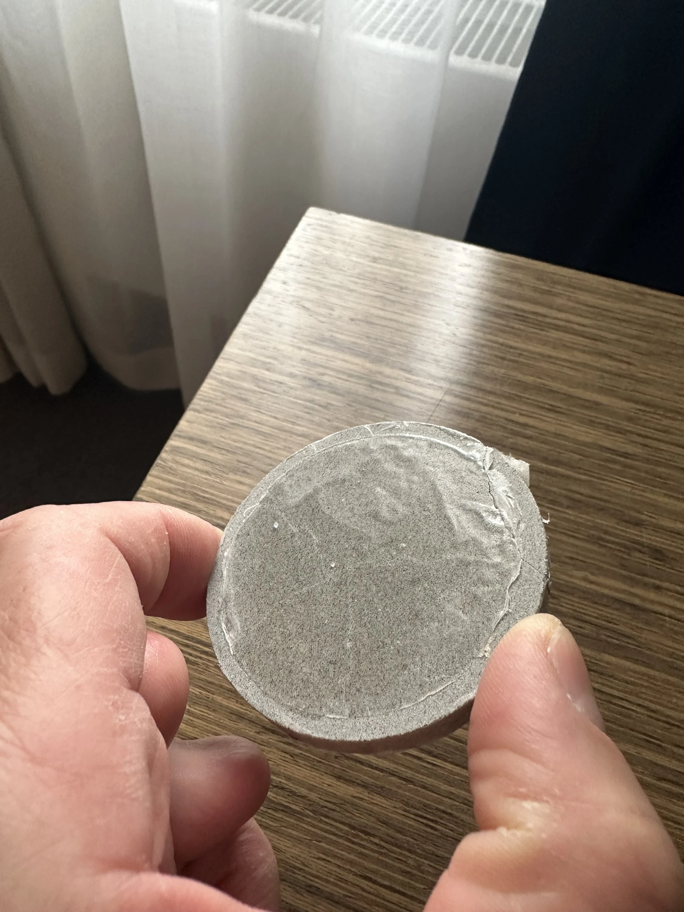
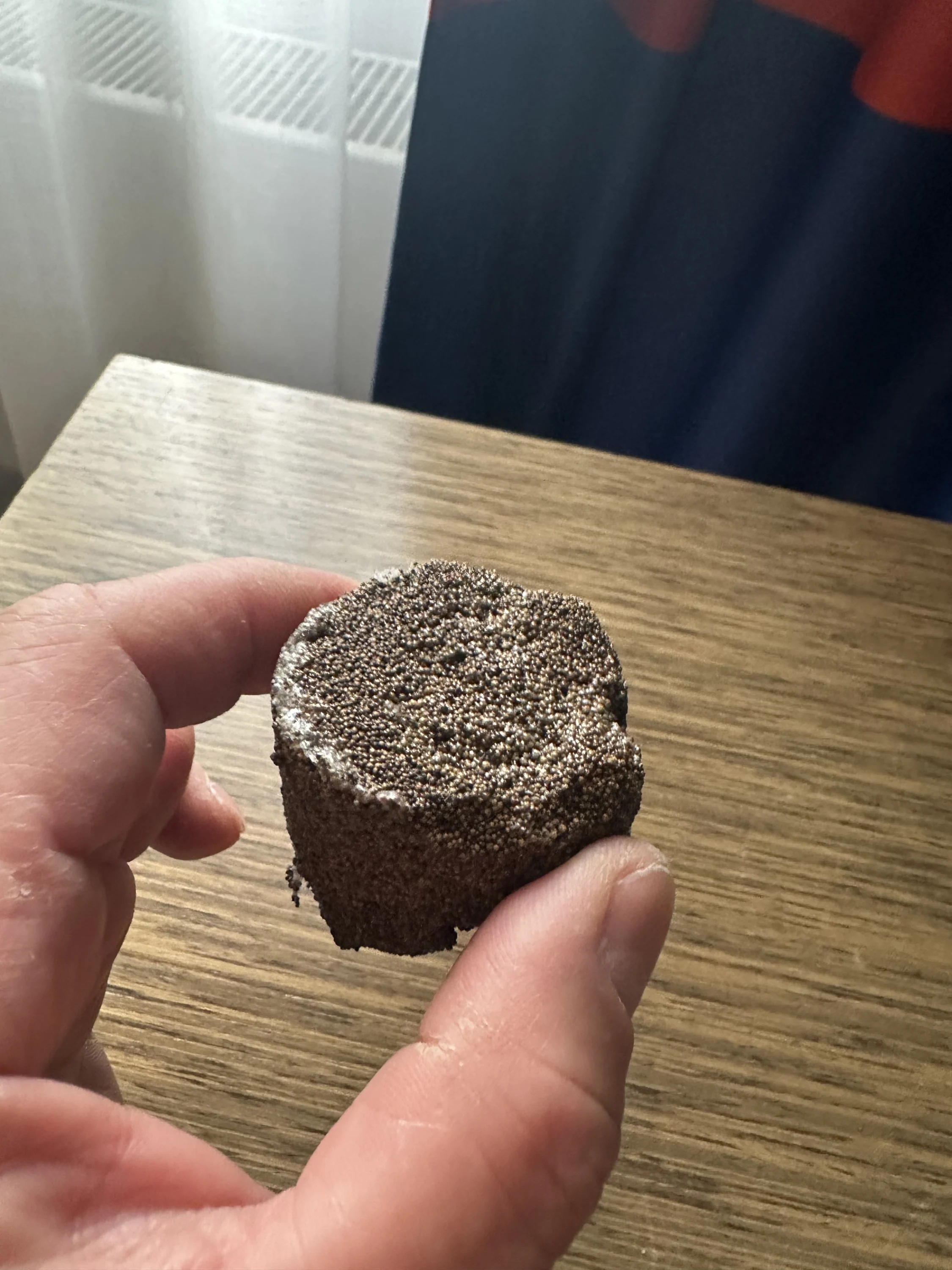
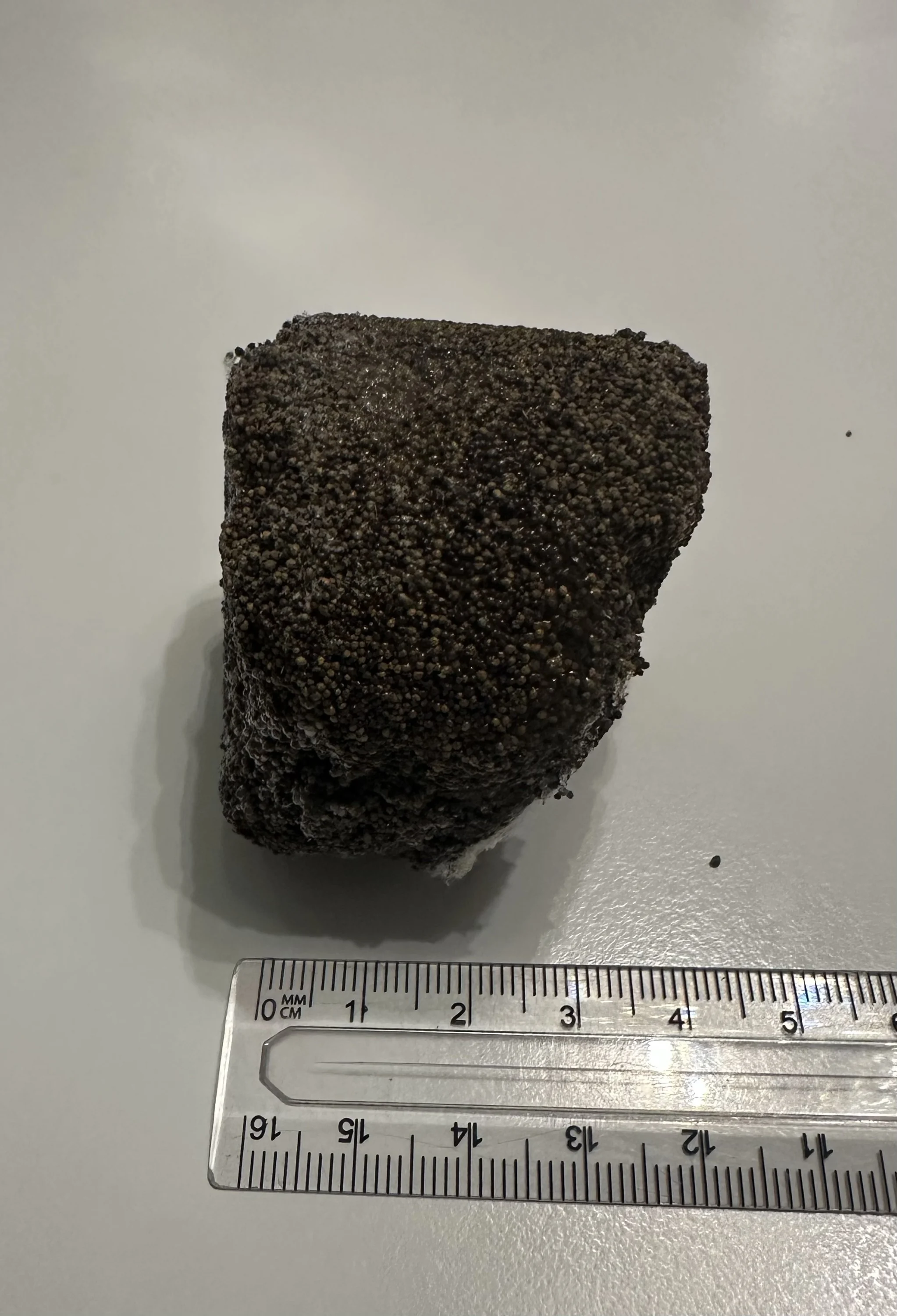
Selected field results. Wells and operators are not named. References from current clients are available on request.
Problem Losses 45–48 m³/h in depleted sands; LCM and another sealant failed
Treatment 1 stage through a BHA with MWD: 6 m³ THERMOGEL HT, 6 m³ gelation activator, 6 m³ THERMOGEL
Result Zero injectivity at ECD 1.17 sg; 500 m drilled to TD at full flow rate, including 50 m of over-pressured formations
Problem Catastrophic losses; 140 days of failed attempts; 240 m³ of 1.76 sg mud lost
Treatment THERMOGEL HT with support on bottom, 3 stages, 79 m³
Result Zone isolated in 6 days; well saved from abandonment
Problem Total losses at 64 and 167 m in fractured hard rock; 40 days of failed attempts
Treatment THERMOGEL with dry THERMOGEL as swelling LCM, 2 stages, 25 m³
Result Both zones isolated in 2 days
Problem 38 m interval, formation pressure 65 bar, pressure coefficient 0.17
Treatment 10 m³ THERMOGEL
Result Gel screen held 285 bar differential during further drilling
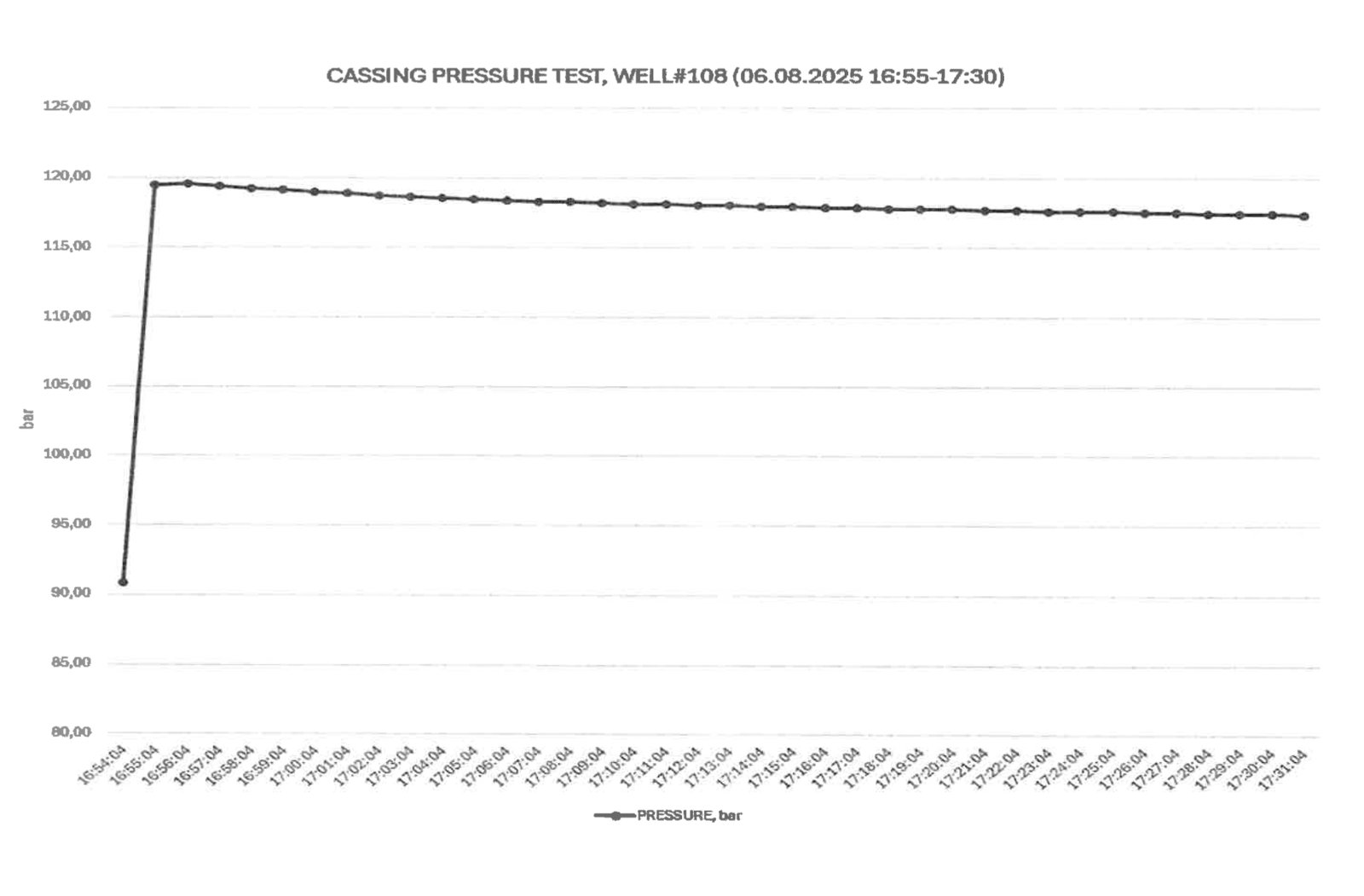
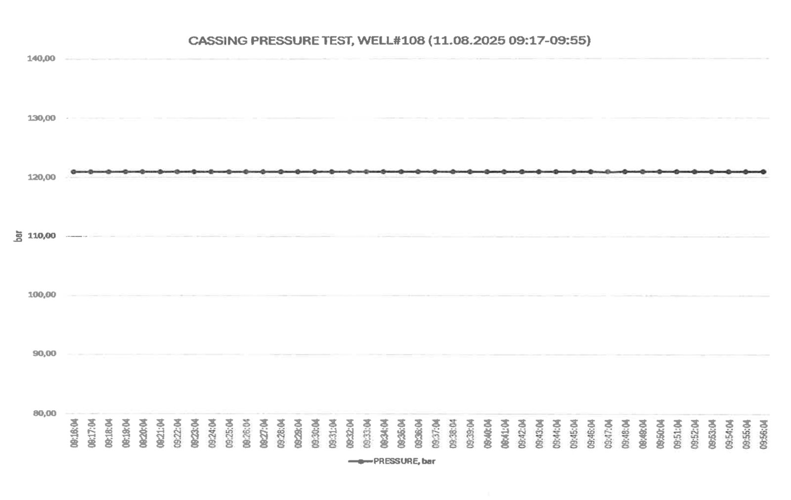
Problem Leak 500 → 305 bar in 30 min
Treatment THERMOGEL, staged over the full casing length
Result Pressure test 500 bar, no decline
| Application | Jobs | Success criterion |
|---|---|---|
| Production casing leak remediation | 269 | Casing fully tight |
| Water shutoff in producers | 30 | Water inflow isolated, water cut reduced |
| Behind-casing crossflow elimination | 20 | Behind-casing flow eliminated |
| Lost circulation while drilling | 19 | Drilling resumed without losses at the required mud weight or ECD and flow rate |
| Conformance control in injectors | 13 | Injection profile improved |
351 treatments since 2004 — 306 THERMOGEL, 45 THERMOGEL HT; about 85% technical success; repeat treatments no more than 2%.
Main operational risks and how we control them.
Water spacer between the two fluids; volumes tracked as a running total with fixed control points. No such event in any of our jobs
Gelation temperature set above circulating temperature; no long stops while the fluid is in the pipe
Squeeze rate lowered to keep surface pressure below the agreed limit
Bit above the zone, exact displacement volume; in well integrity jobs the producing interval is isolated first. Gel is removable with acid
Soft gel, standard bit; gel pieces removed by the shakers; no change of mud rheology or filtration observed
We provide each treatment as a complete service:
Documents: technical data sheets (download); safety data sheets and the laboratory report on request.
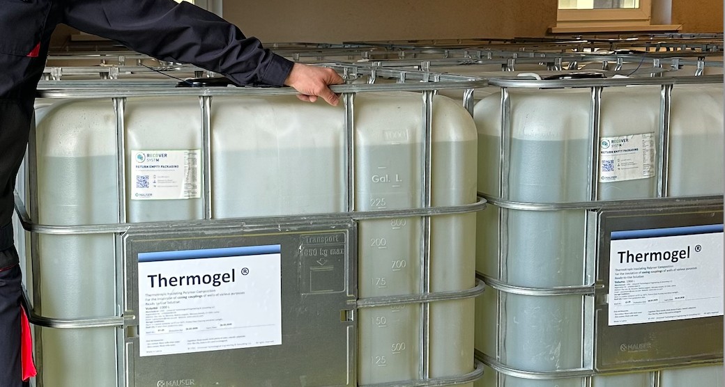
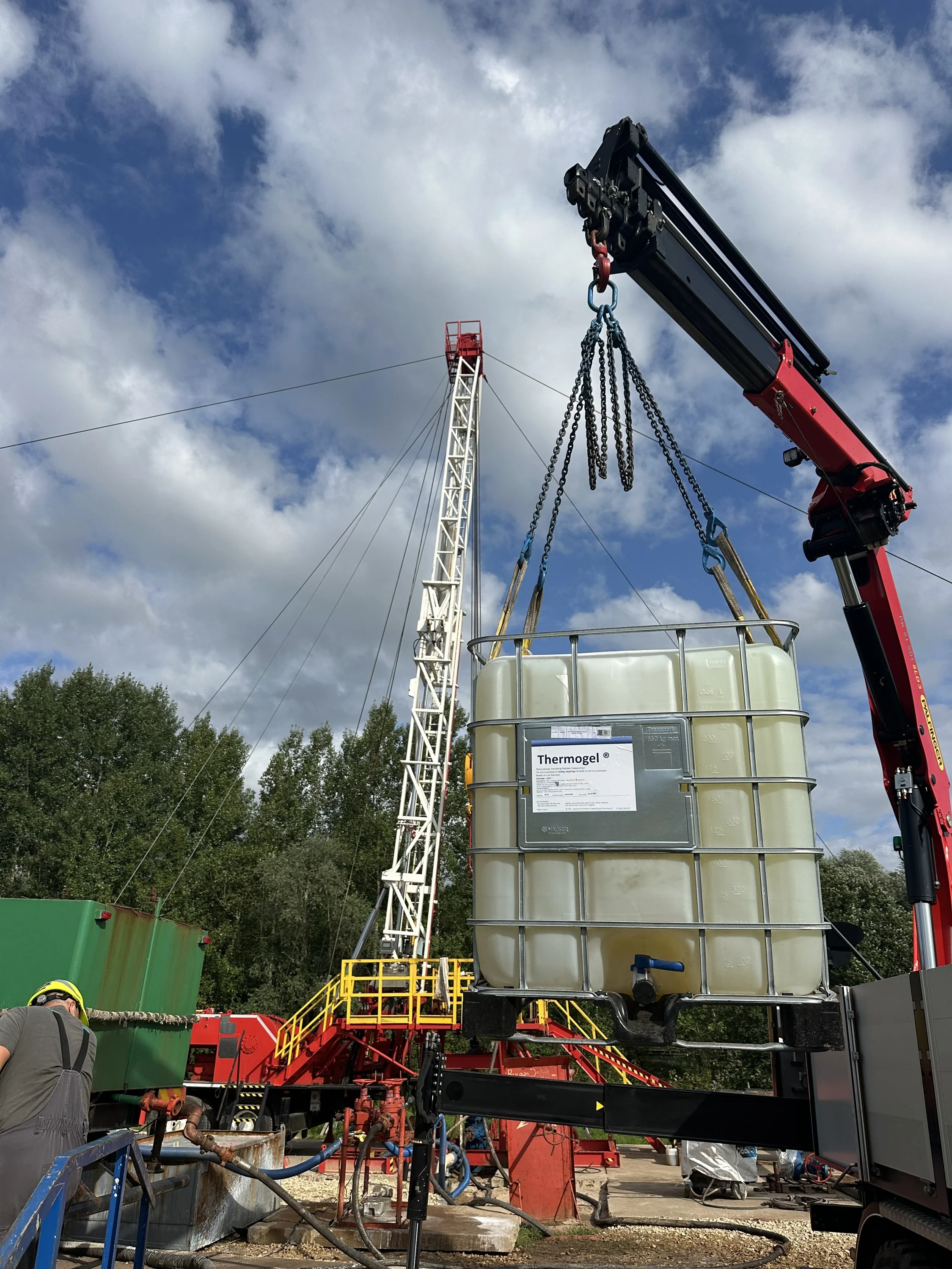
Send us your well data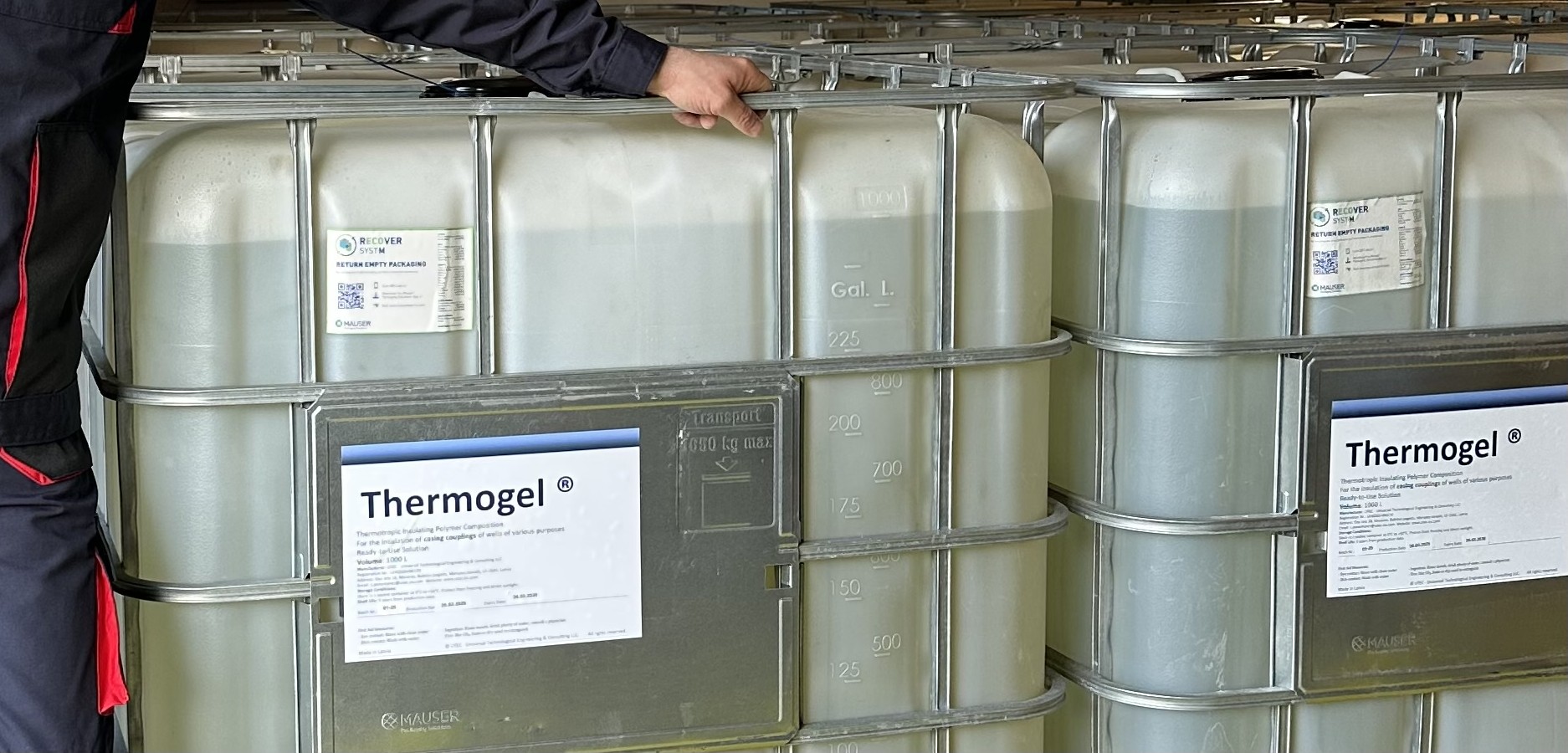 THERMOGEL ready-to-use solution before dispatch
SIA “UTEC – Universal Technological Engineering & Consulting”
Reg. No. LV40203496170
Ošu iela 18, Mežāres, Babītes pagasts, Mārupes novads, LV-2101, Latvia